1926 Chopped Model T Ford Coupe - RAT ROD
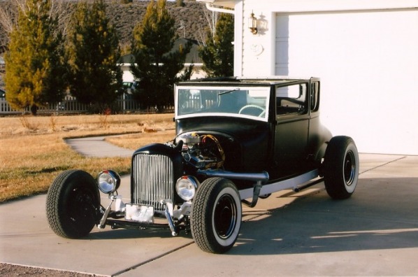
This car was fun to build. I built it for a really good friend of mine and just an all round great guy !!! The frame is home built and extended about 14 inches like a dragster. This is the effect he wanted to represent. It handles great at speeds, but not so good in the turn around in the street or parking lot area! To long of a wheel base. It rides great and is really comfortable since I built the seats very custom to fit his legs. He lost his legs in Viet Nam and wears prosthetic legs. WE call him – Jack the Rat !
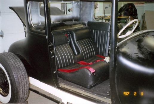
Here’s the custom interior. Notice the under the thigh end of the seat. It is really kicked up so that it will support his stumps and take the pressure off the artificial legs. This is the forth interior that I have done on hot rods. Still not a pro or even close. Just inexpensive and comfortable. The only body work that I did was a little on the firewall. The chop was already complete and Jack finished the chop on the doors and did all the rest of the body work on the car. He did a truly super great job!! Way to go Jack!
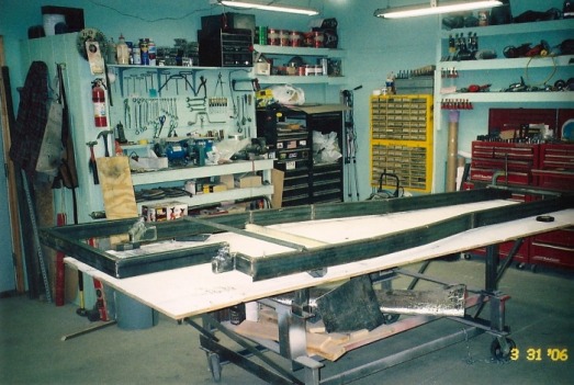
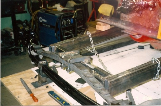
Well here we go. This is where all good rods begin.- the frame. As you can see, I have a piece of plywood on a metal cart that I use to build all of my frames. I paint the top flat white, set the body on top and centered. And then mark the outline of the body with a sharpie pen or take flat black paint and dust the body against the table to show the outline. From here, the frame is designed. I mark reference points – the firewall location and the center of the wheel well. Then the frame is laid out on the table with a 1 ½ inch width to show how the frame is going to contour. This is done with a straight edge and a sharpie pen. My DVD from Streetrod 101 shows exactly how to go about this and how it is contoured, squared, and fit.
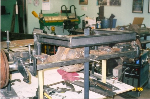
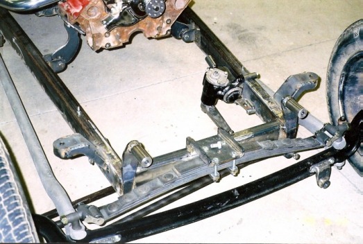
The rear of the frame is made of 1 ½ x 3 x .188 wall tubing and the side rails are 1 ½ x 4 x .188 wall tubing. This picture also shows the use of a lot of clamps and steel that is used to mock up brackets so that alignment and centering can take place in order to tack these pieces in place prior to welding. It’s easier to spend an extra 30 minutes in set up than to have to go back and cut and clean things up because it is not right. I always allow at least 5 to 6 inches of clearance above the axle on an unsprung chassis . Remember that the whole frame will settle down 1 ½ to 2 inches and then you still need to have at least 3 to 4 inches of clearance for spring travel. You don’t want this frame to smack the rear end if you hit a good bump with you and your friend in the car.
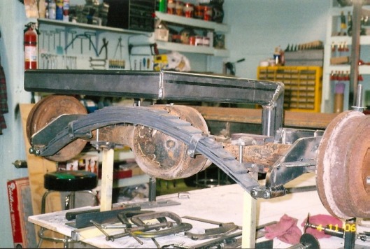
The rear end is supported by stands and the spring is in place on the axle. Now I can see how and what needs to be done in order to build a spring mount off the frame. Sometimes a separate crossmember must be built to accommodate the spring and rear shocks. Notice also, that the spring shackles are almost flat or parallel the ground.
On to the front end. Remember, I like to build from the back to the front – this way I push all the wrinkles forward and everything fits the way I want. Using stock Ford wishbones is cool! The only thing to remember is to build in the caster, because once installed, there is no way to adjust this without some major work. There are several ways to do this. The easiest is to set the rear of the wishbone and bracket where you want it and then “ v” notch the wishbone at the front with the axles tipped back 4 to 6 degrees. Weld it up and hope it goes down the road the way you want it to. Another way is to build an adjustable rear wishbone bracket with removable plates with the hole in a different place within the allowed size of the plate. This is more complicated – so I won’t go into it here. I did use this on a model A roadster years ago and it worked pretty good. Another way , is to cut the wishbone completely off of the mount in front, set your axle to the proper caster angle and then cut the wishbone to match that angle and reweld it. This is similar to the “v” notch – except you are cutting clear through and not guessing what or how much “ v” to cut. Your choice. There are a couple of other ways to do this , but we don’t have the space to go through these. On the rear open end of the wishbone, I just machine a bung and thread it for either a tie rod end or a urethane rod end. The urethane rod end is my preference and it is a 5/8 x 18 thread. If you are going for old school look, then the tie rod is the way to go. They both work well – I just prefer the rod end. I don’t recommend heim joints as they are subject to easier failure. But I have also used them in the past.
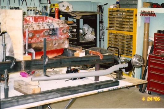
The front spring is a suicide type and notice that the axle is held in place and at the correct height for the tires to be run. Measure from the center of the tire diameter and work down to establish the height of the stands. The ride height in the front and the rear is important when building any type of hot rod. This allows you to build to fit the stance and clearance you want and need. Spring perches are varied as to design. You need to make sure that it is gusseted and strong enough to do the job and make sure it doesn’t interfere with the radiator, shock mounts , or headlight mounts.
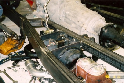
Jack wanted power brakes on this ride so some engineering was needed. Because of space and where the pedal needed to be. I had to mount the power booster to the left of the brake pedal. This required that I build a cross shaft w ith legs on it similar to a bell crank except with just the ears on the shaft. All this does is transfer the rear motion of the brake pedal to the shaft and transfers through the shaft and moves the force over the required distance and continues the rear ward motion to the booster and master cylinder. I use hiem joints for the two rods : two from the pedal to the bell crank and two from the other end of the bell crank to the booster. It actually works very well and performs great ! You do have to fabricate some plates to support the bell crank and the shaft is supported with a bushing on each end.
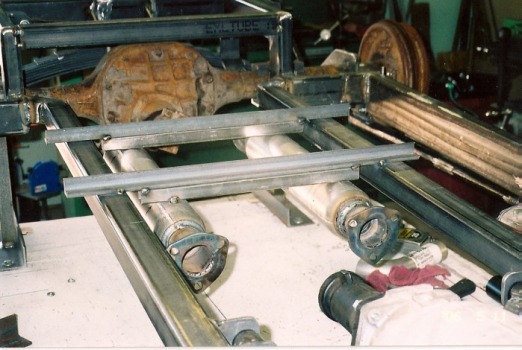
Here is an easy way to hold your mufflers in place while you build the exhaust from the manifolds to the mufflers and from the mufflers to the outside or rear of the car. I just tacked a piece of one inch tubing to the muffler ( this gives me the clearance to the floorboard ) and then tacked a piece of longer angle iron to that and then tacked the angle to the frame. When all is done and the rear hangers are on the pipes to the frame cut the tacks loose and you are finished.
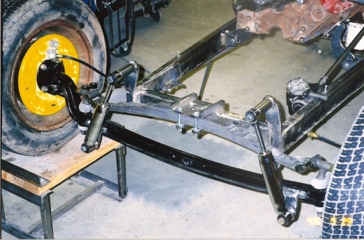
Upper shock mounts were made from ½ plate and were welded to the open end of the frame. I need to tell you that I tapered the front of the frame from just in front of the front wishbone bracket to the front of the front cross member . So the taper actually goes from the 4 inches up to the front cross member which is made of 1 ½ x 3 x .188. This breaks up that wide look and ties it all together very nicely..Caution : If you use a torch to cut the taper , as I did , tack a piece of 1 x 1 or 1 x 2 solid bar stock to the back ( top) of the frame prior to cutting. If you don’t the tubing will actually bow upwards about ¼ of an inch. Just thought I would share that with you. The lower shock mounts are fabricated so they will bolt to the axle and in this case clear the lower part of the I- beam axle.
The front end is really coming together now. The big ears coming off the sides are for the headlights to mount on. You can also see the motor mounts and the Vega steering box in place.
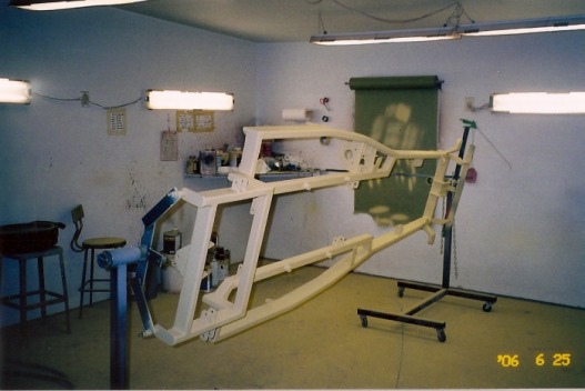
Mounting the frame on a pair of homemade engine type stands makes it super easy to do the finish welding , priming, sanding, etc. My booth is small 16 by 16 and works very well.
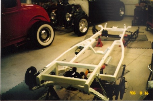
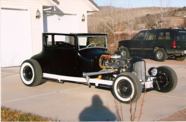
It takes awhile to get to this point. The frame is painted ( white – the fluorescent lights distort colors in pictures terribly) The front end and rear end along with the=2 0front and rear wishbones are painted black. The cars in the back belong to my son in law. The red one is a 1932 original 5 window and the roadster is a 1932 Brookville. We built these together in my shop a few years ago.
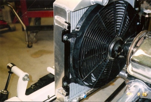
Mounting the electric fans is always interesting . I don’t like to use the zip ties that are provided with the fans. They loosen up in just a short period and look really hokey!!! I try and use the grill shell mounting brackets to mount the electric fans. Looks and functions much better.
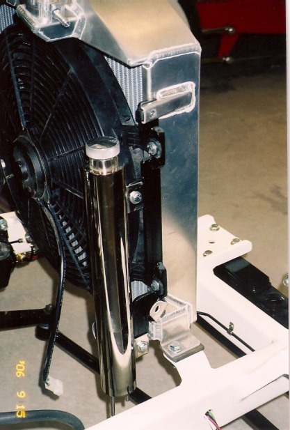
This pictures shows how the radiator , fan, and overflow tank are mounted. Whe n I order my radiators, I have them built without the bo ttom foot that is usually used to mount the radiator. Then I build a bracket that bolts to the grill shell brackets on the radiator and I mount the fan to that also. This radiator was purchased by Jack and so I used the feet that were already on the radiator. These were pretty strong , most are thin pieces of aluminum and are junk.
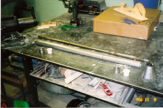
Jack wanted a stock looking nostalgia steering column so I built one out of 1 1/2in. exhaust tubing and hand formed the cone , made the metal sleeves to weld to the tubing and then made the bushings for each end from a nylon material called delrin. The steering shaft is a standard ¾ inch and I took it out of an old column that Jack had. It all came together very nicely. Thank you very much.
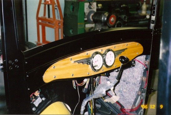
The dash is made from ½ inch Poplar, stained, and then clear coated . Put two coats on, sand with 280 – 320 then shoot again. If need be – cut and buff just like you would a car. It looks cool and holds up to the weather just great.
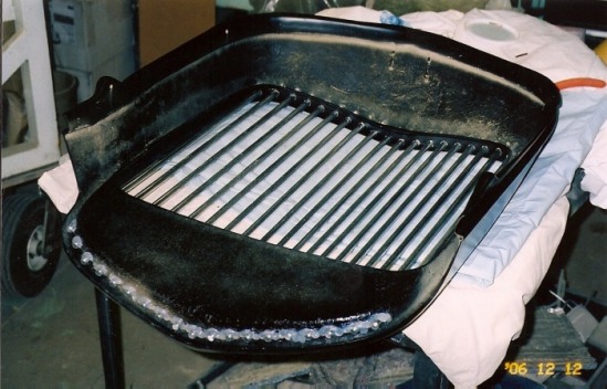
Everyone uses inserts for their grills. I like different and I like vertical bars. So put them together and … here’s what comes out. I use 3/8ths solid aluminum round stock, polished to look like chrome. Measure the center bar and drill upper and lower holes. Then lay out the outside bars ( closest to the shell ) then spit the distance between the center and outside into what ever number of bars you want. Mark the upper then the lower , drill and hand fit. This means use a file and work it out. If you mess up a hole and it is to big – take a small piece of wax paper , wrap the paper around the grill bar and scotch tape it together. Slide the bar into the hole, slide the wax paper trough the hole, and fill the excess area with bondo . When set up, slide the bar out and carefully remove the wax paper and then hand sand the area. Repeat until satisfied. Final assembly: drill a 1/8th inch hole about ½ inch from one end of the grill bar. Slide the bar in through the upper and lower holes with the 1/8th inch hole towards the top of the grille When in place, slide a short ¾ inch piece of 1/8th inch welding rod through the 1/8th inch hole – pull the bar down seating the top against the grill shell. Mark the grill bar about 3/4ths to 1 inch away from the lower hole remove the assembly and cut with a hack saw or disc cutter. Clean the burrs from the end. Put the grill bar back in place and secure at each end with clear silicone. Let dry overnight and then install on the car. Oh – and be sure that the grille shell is painted before doing the final installation of the grille bars!
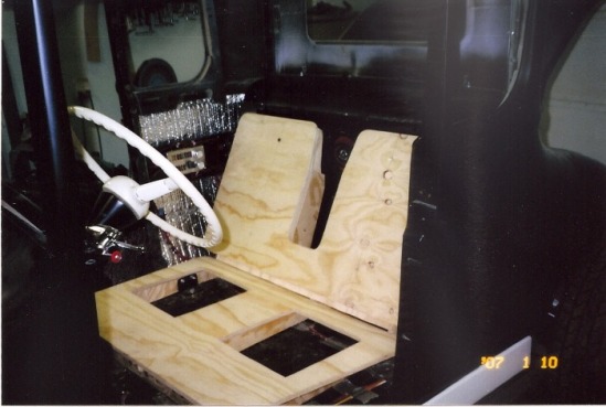
I built the seat frame from ½ inch plywood and glued and screwed and reinforced with blocks in the corners. I make the back separate from the bottom so that when I upholster the seats , it is much easier.
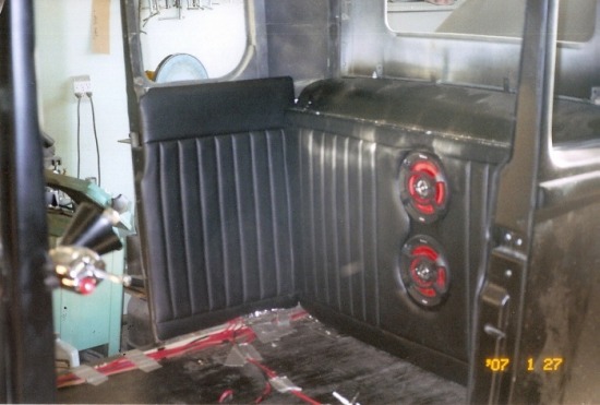
Last shot of the interior showing my home made upholstery with the dual speakers that Jack wanted in the car. I also built 1/8th inch panels for around the windows and upholstered them.
